Admin
Administrator Din: Vechime
Inregistrat: acum 21 ani
Postari: 10086
RTL2832U [Elonics E4000/Raphael Micro R820T] software defined radio receiver.
Originally meant for television reception it was discovered by V4L/DVB kernel developer Antti Palosaari that these devices can output unsigned 8bit I/Q samples at ~2.8 MS/s. A phased locked loop based synthesizer produces the local oscillator required by the quadrature mixer. The quadrature mixer produces a complex-baseband output where the signal spans from -bandwidth/2 to +bandwidth/2 and bandwidth is the analog bandwidth of the mixer output stages. This is complex-sampled (I and Q) by the ADC. Then the ADC samples at 28.8Msps, and the results are resampled inside the RTL2832U to present whatever sample rate is desired to the host PC. This can be 3.2 MS/s but 2.4 MS/s is the max recommended to avoid losing samples. The actual output is interleaved; so one byte I, then one byte Q with no header or metadata (timestamps). The samples themselves are unsigned and you subtract 127 from them to get their actual {-127,+127} value.
The dongles with an E4000 tuner can range between 54-2200 MHz (in my experience) with a gap over 1100-1250 MHz in general. The R820T's go from 24-1700 Mhz. The tuner error is ~30 +-20 PPM, relatively stable once warmed up, and stable from day to day for a given dongle. For the data transfer mode USB 2 is required, 1.1 won't work.
For the best information stop reading this page right now and go to the rtl-sdr wiki - OsmoSDR by the Osmocom people who created,
librtlsdr - contains the major part of the driver rtl_sdr, rtl_tcp, rtl_test - command line capture tools and utilities gr-osmosdr - gnuradio source block
Do not use the dvb drivers on the CD or your OS. Those are for the dvb mode and not the debug mode that outputs raw samples. Linux 3.x kernel should check with "$ lsmod dvb_usb_rtl28xxu" and if found at least "$ sudo modprobe -r dvb_usb_rtl28xxu" to unload it.
SDR# is probably the best application to start out with but you'll have to compile from svn for linux+mono because of some non-portable mono ifdef's during building. Alternately, try gqrx for OSX (precompiled) or linux. multimode is good for linux if you have GNU Radio. For low cpu power and low ram devices try rtl_fm. On that note stevem provides rtlsdr and related tools for openwrt.
This page is mostly just notes to myself on how to use rtlsdr's core applications, 3rd party stuff using librtlsdr and wrappers for it, and lots on using the gr-osmosdr source in GNU Radio and GNU Radio Companion, Freenode's ##rtlsdr and reddit.com/r/rtlsdr were particularly helpful in getting the software running.
I bought two E4000 based rtlsdr usb dongles for $20 each in early 2012. Then many months later I bought two more R820T tuner based dongles for ~$11 each. Of the E4Ks the Newsky TV28T (yellow) was from ebay and arrived within two weeks, well before the DealExtreme dongle arrived. The (green) ezcap EzTV668 was from DealExtreme, payed for on March 25th (2012) and delivered on May 20th. There's a photo of an R820T tuner based dongle in the "mini" format off to the left. It and the Newsky dongle are MCX. Some of the cheaper dongles occasionally miss protection diodes but the last three I've bought have been fine. The antenna connector on the ezcap is IEC-169-2, Belling-Lee. I use a PAL Male to F-Connector Female with it and F to MCX for everything else. Tuners
Only two tuners are very desirable at this time. The Elonics E4000 and the Raphael Micro R820T. In general they are of equal performance but the sticks with R820T chips are much easier to find and cheaper ($10 USD). The E4K is better for high end (>1.5Ghz+) while the R820T can tune down to 24 Mhz without any mods.
All of the dongles have significant frequency offsets from reality that can be measured and corrected at runtime. My ezcap with E4000 tuner has a frequency offset of about ~44 Khz or ~57 PPM from reality as determined by checking against a local 751 Mhz LTE cell using LTE Cell Scanner. Here's a plot of frequency offsets in PPM over a week. The major component of variation in time is ambient temperature. With the R820T tuner dongle after correctly for I have has a ~ -17 Khz offset at GSM frequencies or -35 ppm absolute after applying a 50 ppm initial error correction. When using kalibrate if the initial frequency error too large the FCCH peak might be outside the bandwidth. This would require passing an initial ppm error parameter (from LTE scanner) -e . Another tool for checking frequency corrections is keenerd's version of rtl_test which uses (I think) ntp and system clock to estimate it rather than cell phone basestation broadcasts.
2012-08-22: The E4000 tuner datasheet has been released into the wild. Elonics-E4000-Low-Power-CMOS-Multi-Band-Tunner-Datasheet.pdf, but...
"All the ones that are documented in the DS are 'explained'in the driver header file ... And the rest, the datasheet call them "Ctrl2: Write 0x20 there" and no more details"
2012-09-07: Experimental support for dongles with the Rafael Micro R820T tuner that started appearing in May has been added to rtl-sdr source base by stevem. These tuners cover 24 MHz to 1766 MHz. They also don't have the DC spike caused by the I/Q imbalance since they use a different, non-zero, IF. On the other hand, they might have image aliasing due to being superheterodine receivers. See stevem's tuner comparisons. On 2012-09-20 the R820T datasheet was leaked to the ultra-cheap-sdr mailing list. The official range is 42-1002 Mhz with a 3.5 dB noise figure. On 2012-10-04 my order arrived. I'm liking this tuner very much since it actually works well, locking down to 24 Mhz or so *without* direct sampling mode. Here's a rough gnuplot spectral map of 24 to 1700 Mhz over 3 days I made with some custom perl and python scripts. Don't judge the r820t on the quality of that graph, it is just to show the range. You can see where the front-end gets massively overloaded by pager transmissions which then appear broadly stretched over the high frequencies. I do almost no processing of the signal (ie, no IQ correction), don't clear the buffer between samples (LSB probably bad), and use a hacky way to display timeseries data in gluplot. Real SDR software like SDR# shows them to be equal in quality to E4ks.
stevem did gain measurement tests with a few dongles using some equipment he had to transmit a GSM FCCH peak, "which is a pure tone." This includes the E4000 and R820T tuners. In addition he measured the mixer, IF and LNA for the R820T. High Frequency (0-30Mhz) Direct Sampling Mod
Steve Markgraf of Osmocom has created an experimental software and hardware modification to receive 0~30Mhz(*) by using the 28.8 MHz RTL2832U ADCs for RF sampling and aliasing to do the conversion. In practice you only get DC-14.4MHz in the first Nyquist zone but the upper could be had by using a 14.4 MHz to 28.8 MHz bandpass filter. In the stereotypical ezcap boards you can test this by connecting an appropriately long wire antenna to the right side of capacitor 17 (on EzTV668 1.1, at least) that goes to pin 1 of the RTL2832U. That's the one by the dot on the chip surface. Apparently even pressing a wet finger onto the capacitor can pick up strong AM stations. This bypasses static protection among other things so there's a chance of destroying your dongle. For gr-osmosdr the parameter direct_samp=1 or direct_samp=2 gives you the two I or two Q inputs.
Differential input
Since then the direct sampling branch has been integrated into main and a number of people have also done balun stuff to use both RTL2832U ADC inputs (usually the two I) in direct sampling mode. Dekar has a page showing how to use an ADSL transformer to generate signal for the ADCs differential input using pin 1 (+I) and 2(-I) on the RTL2832. mikig has a useful pdf schematic with part numbers for using wide band transformers or toroids for winding your own. Here's a series of photos showing how to use a FT37-43 ferrite core. The ADC has a differential/balanced input so this is done mainly for the unbalanced->balanced conversion. But the ADC input pins also have a DC offset so you can't just connect one to GND for that. Impedance matching can be done as well but the impedance isn't known. ~200 Ohms seems reasonable and is mentioned in some of the tuner datasheets. 4:1 baluns that are used for cable-tv might also work, depending on the impedance of your antenna.
If you're particularly interested in HF work then an upconverter would be better than the HF mod. With the mod there will be aliases(*) for any frequency over 14.4 Mhz (1/2 the 28.8 clock rate). And probably other little idiosyncracies. A lot of people chose to just use an upconverter instead. KF7LE wrote up short summaries comparing 16 popular upconverters. Sample rates
When setting sample rates in your own programs or scripts try to use one of the values shown in, If it's an end-user app like SDR# or Gqrx then it handles all this for you in the background. It's handy for writing pyrtlsdr scripts though.
range += osmosdr::range_t( 250000 ); // known to work range += osmosdr::range_t( 1000000 ); // known to work range += osmosdr::range_t( 1024000 ); // known to work range += osmosdr::range_t( 1800000 ); // known to work range += osmosdr::range_t( 1920000 ); // known to work range += osmosdr::range_t( 2000000 ); // known to work range += osmosdr::range_t( 2048000 ); // known to work range += osmosdr::range_t( 2400000 ); // known to work // range += osmosdr::range_t( 2600000 ); // may work // range += osmosdr::range_t( 2800000 ); // may work // range += osmosdr::range_t( 3000000 ); // may work // range += osmosdr::range_t( 3200000 ); // max rate
Noise, shielding, and cables.
The plastic cases the dongles ship in leads electrical interference susceptability. It is best to shield them if you can. Acinonyx describes one way to doing this using a single strip of aluminum tape combined with a spring to connect it to the dongle ground. I wrap the entire pcb, except the grounds on the connectors, with kapton tape and then use a single continuous piece of aluminum foil tape to wrap the rest of the dongle. This is easiest with minis. Even sealed with aluminum tape they seem to dissipate heat and reach thermal equilibrium fine in terms PPM error.
Another way to minimize electrical noise is to use a long USB *active* extension cable with hubs at the end and ferrites added. The 10 meter long active USB extension cable I bought seems to decrease the noise floor as compared to directly hooking up to my computer's USB ports. Additionally it lets me place my dongle directly on the antenna feed outside without the signal loss of coaxial cable. Broadband Antenna
When I want to do some scanning that takes advantage of the tuner's very wide ranges I use three types of antenna: discones, spirals, and horns. Both discones and archimedian spiral antenna can omnidirectionally cover almost the full range of the E4000 tuner but things get a bit too large to go all the way to the 24 Mhz of the R820T. You can refer to the seperate spiral antenna page for construction and technical details. To build my discone I followed Roklobsta's D.I.Y. Discone for RTLSDR.
When using such broadband antenna it is possible to pick up powerful out of tuner band signals due to overloading. You can see an example of how bad this interference can be in raw sample total power measurements over time x frequency in these 2D spectral maps: 1, 2. Or in the 1D spectrum plot below,
The powerful pagers (?) near 155 and 930 Mhz, and the university's multiple 45 watt ~460 Mhz transmitters across the street appear aliased (?) all over into other frequency bands. Nasty. In the future I hope to notch them out with physical filters. The linked plot above is made with this gnuplot format and the csv output of RTLSDR Scanner using 1 second integration times with a wire discone.
The spectra and noise baselines are much cleaner when using directional and resonant antenna instead of wideband omnidirectionals like I've been using to characterize the RFI environment.
patchvonbraun suggested doing a frequency sweep with a shielded terminated resistor and then subtracting that sweeps' results from the antenna scans. RTLSDR Scanner's sweeps for the same range and sample rate always match up on frequencies. So it should be just subtracting the corresponding elements of the sorted value pairs from antenna and resistor using self.spectrum.iteritems() in RTLSDR Scanner or using unix tools with the csv.
pus acum 13 ani
Admin
Administrator Din: Vechime
Inregistrat: acum 21 ani
Postari: 10086
Most of sdrsharp vids on youtube were recorded with camstudio ) which is free The main Set 854x480 which is a native resolution of the player in 16:9 format.
Camtasia also is pretty nice because it provides some editing tools.
Another is " Jing " ), same folks that do camtasia.
pus acum 13 ani
Admin
Administrator Din: Vechime
Inregistrat: acum 21 ani
Postari: 10086
RTL2832 - R820T vs tuner RTL2832-E4000
Stickurile dongle USB in combinatia RTL2832 cu tunerul R820T, sunt relativ noi pe piata, mai ales de cand cele cu tunerul E4000 sunt pe cale de disparitie, in urma falimentarii fabricii producatoare.
Principala diferenta a acestui nou tip de tuner, este ca el foloseste o arhitectura LOW-IF de 3.57Mhz, in loc de ZERO - IF ca la cele de pana acum.. Acest lucru se reflecta in faptul ca nu vom mai avea pe mijlocul spectrului "spike-uri" de purtatoare ca la E4000. iata si schema bloc a tunerului R820T :
Inca un plus, este dioda de protectie de pe intrarea antenei care, la acest tip de Stick, este prezenta pe cablaj
Datele de catalog, specifica domeniul de lucru intre 42Mhz -1002Mhz.
Partea superioara se pare ca este corecta, la frecventa de intrare inferioara, am constatat ca incepe sa receptioneze de la cca.22Mhz !
Banda de CB
Banda de 10M
in urma testarii simultane (dar si la prima vizualizare), am vazut o diferenta de castig de +10dB cel putin, la receptorul cu R820T, ca si lipsa semnalelor "in oglinda" sau "fantome". Testul l-am facut cu o singura antena de la care prin splitter ( 0dB atenuare) a fost distribuita la cele doua stick-uri; acelasi soft deschis in doua ferestre simultane si pe acelasi computer, desigur. Diferenta sau rezultatul, se poate vedea in clipul de mai jos:
Concluzia, este ca merita sa achizitionati un asemenea gadget, cu toate ca nu ajunge pana la frecvente asa superioare ca E4000 dar, aveti avantajul receptiei in cele HF (24-27-28-50 Mhz) Cum spunea amicul meu Liviu - YO2LAU, e ceva sa poti vizualiza toata banda de 50Mhz vara, cand se deschide propagarea si vezi cam pe unde sunt corespondentii ! Eu personal preferam sa vad si banda de 14Mhz dar, nu le putem avea pe toate! Astept si concluziile voastre, succes la receptii interesante si DX-uri !
***
pus acum 13 ani
Admin
Administrator Din: Vechime
Inregistrat: acum 21 ani
Postari: 10086
The hardware mod is quite simple for someone with good soldering skills. It involves opening the dongle casing, and soldering a random wire or long wire antenna to pin one or pin two (or 4 or 5) of the RTL2832U chip. This allows RF signals to directly enter the RTL2832 chip by bypassing the tuner chip. Even a short wire a few centimeters long will be sufficient for picking up broadcast AM stations. For ham signals and international broadcasts, a longer wire placed up high is probably required. Care must be taken with the mod as this bypasses all electrostatic discharge (ESD) protection.
Pin one and two are located below the circle indentation on the RTL2832U chip. It might be easier to solder the wire to one of the two capacitors which are connected directly to pin one and two.
RTL2832 Pin 1 and Pin 2
Some more useful images of pin layouts can be found at superkuhs RTL-SDR blog post.
If you are using an R820T tuner it may be best to use pins 4 or 5 for this mod as due to its architecture they are actually unused. This will allow you to use normal quadrature sampling as per normal for VHF and UHF frequencies and direct sampling mode as well. The problem with these pins is that they do not have a capacitor connection, thus making them very hard to solder to. Software Settings
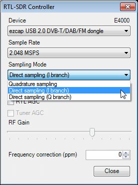
Activating direct sampling mode requires a software driver adjustment. Luckily, SDRSharp has this adjustment as a built in option. In SDRSharp, go to the configure menu, and change the sampling mode to Direct sampling (I branch), or Direct sampling (Q branch). The I branch corresponds to pin one/pin two, and the Q branch corresponds to pin four/pin five.
If a wire antenna is connected to any one of these pins, and the correct direct sampling branch is selected, you will be able to receive signals between 0 14.4 MHz. Frequencies between 14.4 and 28.8 MHz can also be received by using a band pass filter.
SDR Sharp Direct Sampling Balun Improvement
Since the RTL2832U uses two pins to create a differential input (one pins input is subtracted from the other), a balun can be used to connect both pins one and two to an HF antenna that is not just a simple random wire antenna. Essentially this improvement involves finding or winding your own balun, and connecting the balun inputs to both pin one and two (or four and five), and the other end of the balun to your antenna. Here is a pdf file by mikikg showing schematics for this modification.
Here is a blog post by Dekar who used a transformer from an old ADSL modem as the balun. A blog post here and also another here in Japanese show mods where the balun transformer was wound manually. Another site in Italian with a lot of useful images is here. He used a 4:1 self wound toroid as the balun and got what looks to be good results. Google translate can be used to translate the pages, but the images are the most important things here.
Generally a 4:1 balun is used as the RTL2832U input impedance is estimated at around 200 250 Ohms, but some people claim that higher impedance transformations such as 10:1 work better.
If you dont want to use a balun then it can also help to connect a 1 nF to 100 nF capacitor to ground on the unused pin. Other Improvements
Most experimenters of this mod find that FM interference is a problem and thus low pass filters are necessary. The Italian mod page shows schematics and images of a 60 MHz low pass filter combined with the direct sampling mod. His results show significant improvements in out of band signal rejection with the low pass filter.
Some users also report that adding in a low noise amplifier (LNA) can help improve reception. A good Reddit thread discussing improvements to this mod can be found here.
As the RTL2832U input impedance is unknown, it is difficult to match impedance with the antenna. In Dekars mod, he assumed a 1:2 impedance conversion would help, but it actually made the signal worse. Direct Sampling with No Hardware Modifications (No-Mod)
There is now an experimental driver by Oliver Jowett which allows tuning down to 13 MHz and sometimes even lower down to 1 MHz on a R820T RTL-SDR. When coupled with an LNA and low pass filtering this modified driver can work very well, but not as good as with an upconverter or hardware direct sampling mod. It is also reported that the R820T2 tuner works much better than the R820T tuner with this mod due to its wider filters.
There is also another experimental RTL-SDR driver by tejeez which enables a similar mod that allows HF tuning, but it works through a different mechanism. Most reports say that it is not as good as Oliver Jowetts mod. See a post about this mod here.